| DoDAF∫ÕMBSE
DoDAF is an architectural framework
defined by the United States Department of Defense
(DoD) for the defense and aerospace industries. The
goal is to effectively combine operational objectives,
combat capabilities, and various systems that support
operations, and to effectively coordinate independent
systems through the association of system architectures,
so as to obtain capabilities and achieve goals.
 |
Mission
Protect. Connect. Perform.
Vision
To Deliver an Information Dominant Domain to
Defeat our Nation's Adversaries
Key Focus Areas
Artificial Intelligence. Cloud. Communications.
Cybersecurity. Data.
|
Mission
Defend. Link. Execute.
Vision:
Deliver an information-led field to defend the
nation
Focus areas
Artificial Intelligence, Cloud, Communications,
Cybersecurity, Data
|
DoDAF can be used to organize
and share large, complex distributed system architectures.
DoDAF has 8 viewpoints, as shown in the figure below:
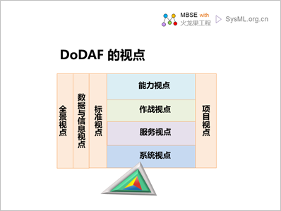
The 8 viewpoints of DoDAF are
briefly described as follows:
|
Viewpoint |
Illustrate |
|
Global Viewpoint (AV) |
Describe
the top-level content of the body architecture
to give the purpose, scope, and context of the
architecture. |
| Capability
Perspective (CV) |
Describes
the capabilities that the organization needs to
have. |
|
Data & Information Perspectives (DIV) |
Describe
the information and rules that need to be managed
and used in the organization's business activities. |
Operational Viewpoint (OV)
|
Describes
the tasks and activities, rules, and resource
flows required to perform the action. |
Service Perspective (SvcV)
|
Describes
the services and interconnections required to
support the operational and business functions
of the DoD |
System Viewpoint (SV)
|
Describes
the systems and interconnects required to support
DoD functionality. |
Project Viewpoint (PV)
|
Describes
how the project is orchestrated and organized
to deliver capability. |
Quasi-Viewpoint (StdV)
|
Describes
the technical standards that the architecture
and its engineering should follow. |
DoDAF has multiple models for
each viewpoint, the following is a list of models
included in each viewpoint:
|
Viewpoint |
Model |
|
Panoramic viewpoint |
AV-1 Overview and Summary Information
AV-2 Comprehensive Dictionary |
|
Competency perspectives |
CV-1: Vision
CV-2: Capability Classification
CV-3: Capability Phase
CV-4: Capability Dependencies
CV-5: Capability to Organizational Development
Mapping CV-6: Capability to Operational Activity
Mapping
CV-7: Capability to Service Mapping |
|
Data and information perspectives |
DIV-1: Conceptual Data Model
DIV-2: Logical Data Model
DIV-3: Physical Data Model |
|
Manipulate viewpoints |
OV-1: Advanced Operations Concept Diagram
OV-2: Operations Resource Flow Description
OV-3: Operations-Resource Flow Matrix
OV-4: Organizational Diagram
OV-5a: Operations Activity Decomposition Tree
OV-5b: Operations Activity Model
OV-6a: Operations Rule Model
OV-6b: State Transition Description
OV-6c: Event Tracing Description |
|
Service Perspectives |
SvcV-1 Service Context Description
SvcV-2 Service Resource Flow
Description SvcV-3a System - Service Matrix
SvcV-3b Service - Service Matrix
SvcV-4 Service Function Description
SvcV-5 Traceability Matrix from Operations Activity
to Service
SvcV-6 Service Resource Flow Matrix
SvcV-7 Service Metrics SvcV-8
Service Evolution
SvcV-9 Service Technology and Skill Prediction
SvcV-10a Service Rule Model
SvcV-10b Service State Transition
SvcV-10c Service Event Tracking Description |
|
System viewpoint |
SV-1 System Interface Description
SV-2 System Resource Flow
Description SV-3 System - System Matrix
SV-4 System Function Description
SV-5a Operational Activity to System Function
Traceability Matrix
SV-5b's Operational Activities on the System Traceability
Matrix
SV-6 System Resource Flow Matrix
SV-7 System Metrics Matrix
SV-8 System Evolution Description
SV-9 System Technology and Skill Prediction
SV-10a System Rule Model
SV-10b System State Transition Description
SV-10c System Events - Trace Description |
|
Standard viewpoint |
Standard Summary
Standard Forecast
|
|
Project viewpoints |
PV-1: Portfolio Relationships
PV-2: Project Timeline
PV-3: Project-to-Capability Mapping
|
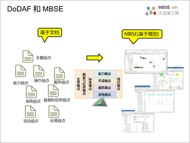
The models in DoDAF's 8 viewpoints
are all interrelated, so that a holistic architecture
can be comprehensively defined from multiple perspectives.
This necessitates a transition from the traditional
systems development process (document-based and code-centric)
to MBSE (Model-Based Systems Engineering) when doing
DoDAF engineering.
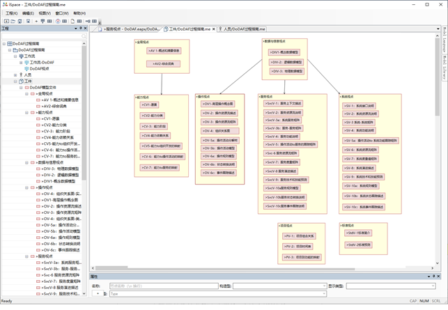
A guide to the process of setting
up a DoDAF using iSpace
Due to the complexity of DoDAF,
it is necessary to understand the relationship between
these models and define what role and what model in
the whole architecture establishment process, which
requires a tool to guide the architecture process
of DoDAF, and iSpace, an MBSE process support tool,
can help users establish a DoDAF process guide and
describe three process views:
Workflow
Personnel roles
Deliverables
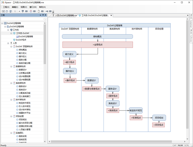
The following is a guide to the
DoDAF process established with iSpace
DoDAF's workflow
First, let's model the DoDAF
workflow as follows:
Roles and responsibilities

Workpiece (deliverable)
What are the models for each
viewpoint of DoDAF? The following is a model mapping
of each viewpoint of the DoDAF created using the MBSE
Process Guide tool iSpace.
DoDAF modeling using UPDM and
UAF
Introduction to using UPDM
and UAF
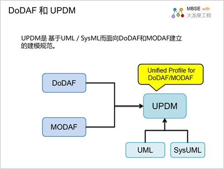
UPDM is a UML/SysML-based modeling
guideline for DoDAF and MODAF. A UPDM group jointly
formed by INCOSE and OMG to use UML /SysML creates
a unified profile for DoDAF and MODAF (UPDM).
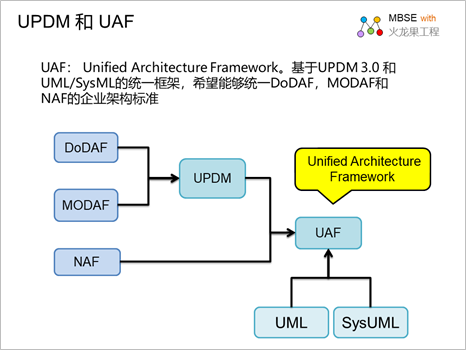
UAF (Unified Architecture Framework£©°£
Based on UPDM 3.0 and UML/SysML unified framework,
we want to unify enterprise architecture standards
for DoDAF, MODAF and NAF. The UAF objective is to
develop a standardized and consistent IT top-level
architecture in the military field based on DoDAF
(United States Department of Defense Architecture
Framework), MODAF (United Kingdom Ministry of Defense
Architecture Framework) and NAF (North Atlantic Treaty
Organization Architecture Framework). UAF defines
an approach to representing the top-level architecture
of IT that enables stakeholders to focus on specific
areas of the organization while maintaining a holistic
view.
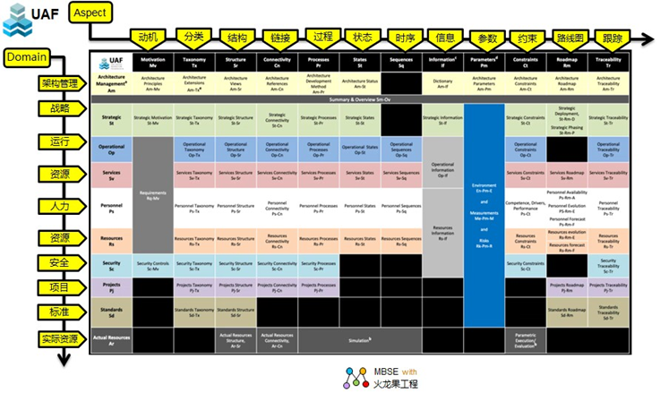
The UAF view specification is
organized using a two-dimensional grid, often referred
to as the UAF Grid:
Rows: 10 domains that
define the domains that the architecture describes.
Columns: 12 Aspects that
define which aspects to model with.
EA's support for UPDM
As a mainstream modeling tool
that supports UML and SysML, EA naturally has support
for UPDM. The modeling tools available in the EA for
UPDM include three aspects:
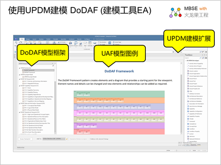
UPDM Modeling Extension:
Provides UPDM modeling symbols and corresponding
model diagrams.
DoDAF Model Framework:
Provides a model organization framework for all
8 viewpoints of DoDAF.
DoDAF Legend: Provides
a legend of all models of the 8 viewpoints of DoDAF.
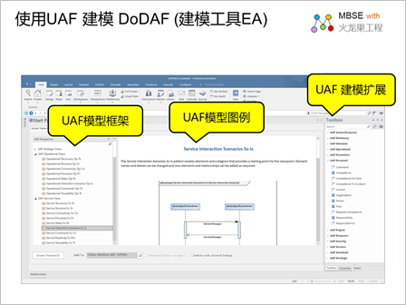
Support for UAF in EA
In addition to supporting UPDM,
the modeling tool EA further provides support for
UAF, including three aspects:
UAF Modeling Extension:
provides UAF modeling symbols and corresponding
model diagrams.
UAF Model Framework:
Provides a framework for organizing all models of
UAF from 12 viewpoints.
UAF Legend: Provides
a legend of all models of UAF for 12 viewpoints.
An example of a DoDAF model
built in an EA
The models of DoDAF from each
viewpoint are strongly correlated, so that the overall
architecture can be decomposed and tracked in an orderly
manner. The modeling tool EA can build models of each
viewpoint and associate each model to achieve overall
modeling and understanding of the architecture.
Below are a few examples of the
DoDAF models that have been built in the EA.
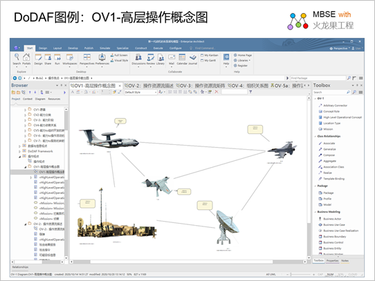
OV1: Concept diagram of high-level
operations
OV-1 describes a task, task category,
or scenario. It shows the main operational concepts
and the operational areas of concern. Describes the
interactions between the system of current interest
and its environment, as well as with external systems.
OV-1 provides a graphical description of the content
of the architecture and ideas about the actors and
operations. Its primary use is to aid human communication
and is intended to be introduced to high-level decision-makers.
Intended uses of OV-1 include:
Put an action situation
or scenario into context.
provide tools for discussion
and presentation;
Provide an informational
description of the published schema in a high-level
organization.
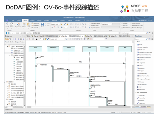
OV-6c - Event Tracing Description
OV-6c provides a chronological
check of resource flows on a case-by-case basis. Each
event trace diagram should have an accompanying description
that defines a specific scenario or situation. The
goal of an operational event/trajectory description
is to track the action in a scene or sequence of key
events, It can be described in a sequence diagram.
Uses for OV-6c include:
Operational event analysis
Behavioral analysis
Identify non-functional
user requirements
Operational test scenarios
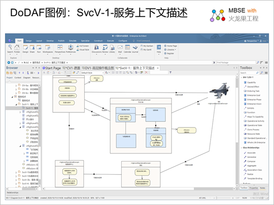
SvcV-1 - Service Context Description
SvcV-1 describes the structure
of resources and how they interact so that operations
in a logical architecture and services from service
perspectives can be linked. It is important for architects
to recognize that SvcV-1 is focused on resource flow
and service delivery. Subservices can be identified
in SvcV-1 as any level of decomposition (i.e., depth)
that the architect deems appropriate. SvcV-1 can also
identify the physical assets (such as platforms) where
resources are deployed, and override the operational
activities and locations that use those resources.
Uses of the SvcV-1 include:
Definition of the concept
of service.
Definition of service
options.
Service resource flow
demand capture.
Capability integration
plan.
Service integration management.
Action plan (capability
and performer definitions).
SvcV-1 is used in two complementary
ways:
Describes the flow of
resources exchanged between resources in the schema.
Describe the solution
in terms of functional components and their physical
integration on the platform and other facilities.
postscript
I hope you have benefited
from reading this.
If you are willing to share
your experience, please submit it to us.
If you are interested in
our training, consulting and tools, please feel
free to contact us at
umlooo@hotmail.com
|