| Introduction
to Time Graphs
Time graphs define the behavior
of different objects over a time scale. It provides
a visual representation of an object's state and interaction
over time. It can be used to:
define
hardware drivers or embedded software components;
For example, those are used in fuel injection systems
or microwave controllers
Specify
a time-driven business process
Time graph elements and connectors
can be generated from the 'Timing' page of the Diagram
Toolbox.
Example of a time graph:
Elements of a time graph
| Icon |
Element description |
Description |
 |
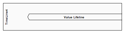
State
lifeline |
A state lifeline represents the state of an object
over a period of time, representing discrete transitions
between states based on changes on the y-axis |
 |
Numerical lifeline |
Numeric lifelines represent the state of an object
over a period of time, and parallel lines along
the x-axis represent a steady state. |
 |
Message labels |
Message labels are another way to represent messages
between lifelines, which is useful for "collating"
a time graph of messages that are scattered around. |
 |
Message endpoints |
The message endpoint represents the message: Terminates
at an undefined point outside of a state or
numeric lifeline and begins at a determined
point within a lifeline
An undefined point that originates outside
a state or numeric lifeline and ends at a definite
point within a lifeline |
 |
Chart entry |
Chart entry means message: Terminates at a
defined point outside of a state or numeric
lifeline, starting at a specified point within
a lifeline
Originates at a defined point outside of a
state or numeric lifeline and terminates at
an identification point within a lifeline |
State lifeline
A lifeline is the path that an
object travels over a period of time, as indicated
by the x-axis. There are two types of lifelines: state
lifelines (defined here) and numeric lifelines, both
of which are used in time graphs.
State lifelines follow discrete
transitions between states, which are defined along
the y-axis of the timeline. Any transition has optional
properties for time constraints, duration constraints,
and observations. An example of a state lifeline is
shown below:
In the example diagram above,
the OK transition point has the following properties:
| Attribute
|
Value
|
| At
Time |
68
ms |
| Transition
to |
Idle |
| Event
|
OK
|
| Timing
constraints |
t°≠t+3
|
| Timing
observations |
®C
|
| Duration
constraints |
®C
|
| Duration
observations |
®C
|
Transfer point attributes
A state lifeline consists of a
set of transition points. Each transition point can
be defined using the following attributes:
| Attribute
|
Description
|
| At
time |
Specify
the start time for the status change. |
| Transition
to |
Indicates
the state to which the lifeline has changed. |
| Event |
Describe
the events that took place. |
| Timing
constraints |
Refers
to the time it takes to change state within a
lifeline, or the time it takes to transmit a message
(e.g., t... t+3) °£ |
| Timing
observations |
Provides
information about the status change or when the
message was sent. |
| Duration
constraints |
Applies
to the time that the lifeline is in a specific
state. Constraints can be caused by a state change
in the lifeline or a message received by the lifeline. |
| Duration
observations |
Indicates
the interval of the lifeline in a specific state
from the time of the state change or message receiving. |
OMG UML Specification:
The OMG UML specification (UML
Superstructure Specification, v2.1.1, p.518) states:
This is the state of a classifier
or property, or some testable condition, such as a
discrete, enumerable value.
It is also allowed that the state
dimension is continuous and discrete. This is illustrative
for scenarios where some entities experience continuous
state changes, such as temperature or density.
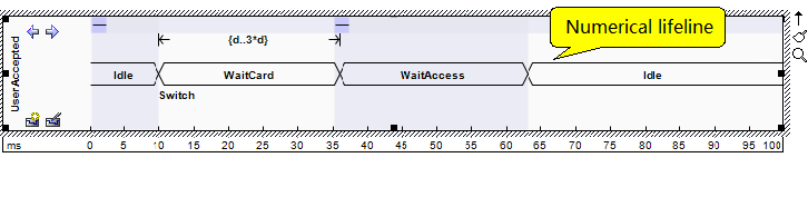
Numerical lifeline
A lifeline is the path that an
object travels over a period of time, represented
by an x-axis. There are two types: numeric lifelines
(defined here) and state lifelines, both of which
are used in time graphs.
Numeric lifelines show the state
of the lifeline in the graph, and parallel lines represent
the steady state. The intersection between the lines
indicates a shift or change in state.
Here's an example of a numeric
lifeline:
In the example diagram, the 10ms
transition point has the following properties:
| Attribute
|
Value |
| At
Time |
10ms
|
| Transition
to |
Waitcard
|
| Event
|
Switch |
| Timing
constraints |
®C
|
| Timing
observations |
®C
|
| Duration
constraints |
d
°£°£ 3*d |
| Duration
observations |
®C
|
The OMG UML specification (UML
Superstructure Specification, v2.1.1, p.518) states:
Displays the value of the connectable
element as a function of time. Values are explicitly
represented as text. Cross-reflect events where the
value changes.
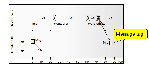
Message labels
Message labels are an alternative
way to represent messages between lifelines, and are
useful for "collating" a time graph of messages
scattered around. To indicate messages between lifelines,
draw a connector from the source lifeline to the message
label. Next, draw a connector from another message
label to the target lifeline. Note that the label
names must match to reflect that the message occurred
between two message labels.
This diagram illustrates how to
construct messages between lifelines using message
labels.
OMG UML Specification (UML Superstructure
Specification, v2. 1 °£ 1 £¨ p °£ 518) states:
Labels are just symbolic shorthand
to keep the chart out of clutter, many messages crisscrossing
between lifelines that are far apart. Tags indicate
that messages can be corrupted by the introduction
of a tag with the same name.
Message endpoints
The message endpoint element defines
the termination of a state or numeric lifeline in
the time graph. It indicates the message:
• Terminates at an
undefined point outside of a state or numeric lifeline
and starts at a marked point within the lifeline
• Originates at an
undefined point outside a state or numeric lifeline
and ends at a definite point inside a lifeline
Chart entry
A chart entry is a simple, graphical
way to indicate where a message can be transferred
to or outside of an interactive fragment. A fragment
may be required to receive or deliver a message; Internally,
ordered messages reflect this need, indicating the
entrance at the boundary of the fragment frame. Any
external messages that are synchronized with this
internal message must correspond appropriately. Portals
can appear in interaction diagrams (sequence, time,
communication, or interaction overview), interaction
events, and combined fragments (to specify expressions).
Relationships with time graphs
| Icon
|
Element name
|
Description
|
 |
Message |
A
message represents the flow of information or
the transfer of control between elements |
Message
Messages are communication links
between lifelines in a time graph. In the case of
Timeline, Message is a connection between two Timeline
objects.
For example
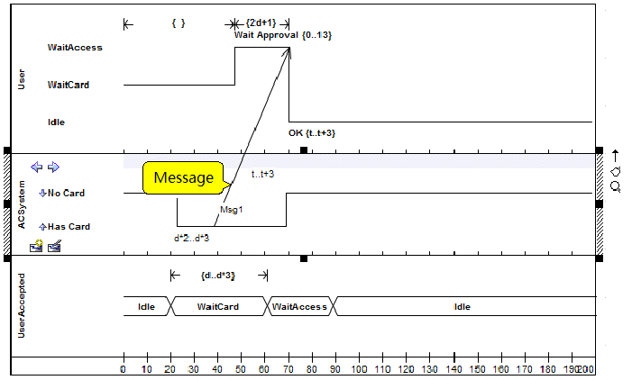
Example: Create a time message
You can create a time message
between two lifeline objects (status or value) on
a time graph, each with an existing transition point.
Here's an example diagram of a
configuration message:
Timing Message Attributes:
| Attribute
|
Illustrate
|
| Start
|
Identify
the lifeblood of the message's origin. |
| End
|
Identifies
the lifeline of message termination. |
| Start
Time |
Displays
the time when the message started after the timeline
started. You can change this setting if you want. |
| End
Time |
Shows
when the message ends after the timeline starts.
You can change this setting if you want, but the
time must correspond to the Transition point on
the target lifeline. |
| Name
|
Optionally,
type a name for the message. |
| Time
Observation |
£®Optionally,
type any text as a label that provides information
about when the message was sent. |
| Duration
Observation |
Optionally,
type any text as a label that provides information
about the lifeline interval in a specific state,
starting with the message received. |
| Transition
To |
The
state in the target lifeline where the message
is terminated. If necessary, you can click the
drop-down arrow and select the different states
you want to transfer to. The head of the message
moves accordingly. |
| Event
|
Optionally,
enter the name of any event that triggered the
Transfer. |
| Time
Constraint |
Optionally,
enter the maximum amount of time it will take
to transfer the message. |
| Duration
Constraint |
Optionally,
enter the maximum amount of time that a lifeline
can remain in a changed state after receiving
a message. |
• The source of the
message can be freely moved along the source timeline;
However, the target side (arrow) must be attached
to a transfer.
• If a new Message
is created and it is not given a target Transfer,
it will automatically find and attach to the most
recent Transfer; If you move the target side, it will
drag and drop the transfer.
If you
would like to learn more:
Welcome to the Modelers Channel
http://www.mbse-x.com/
You are also welcome to contact
us directly at umlooo@hotmail.com
Postscript
I hope you have benefited from reading this.
If you are willing to share your experience, please submit it to us.
If you are interested in our training, consulting and tools:
|